
Home | Net Concepts pg1 | Net Concepts pg3 | Introduction to the Internet
Essential Network Concepts - Page 2
This Study Guide continues with the networking basics topic. We'll walk through the essentials of network transmissions and network cabling. This includes a look at the various cable types commonly found on LANs and their properties, as well as the methods for properly wiring devices and creating Category 5 cables.The topics to be covered in this Study Guide include:
Network Transmission methods
Network Cabling
Creating Cat5 Cables
Straight-through versus Crossover Cables
Network Transmission methods
Transmissions on a Local Area Network can be broken down into three main categories. These include unicasts, multicasts, and broadcasts, each of which is described below.Unicast
A unicast is a one-to-one network transmission. When used, a single system is attempting to communicate with only one other system. On an Ethernet network, unicasts are recognized by the fact that both the source and destination MAC addresses identify unique hosts. On an IP network, both the source and destination IP addresses are unique.
When a system comes into contact with a network frame, it will always check the MAC address to see whether this frame is meant for it. If the MAC address matches that of the destination system, it will process it. If not, the frame will be discarded. Remember, when plugged into a hub, all systems see all frames traveling across the network, because they are all part of the same collision domain.
Multicast
A multicast is a transmission meant for many, but not necessarily all hosts. In that way, a multicast is known as a one-to-many transmission method. Multicasts are used in special scenarios, such as when a group of computers needs to receive a particular transmission. A good example of this would be streaming audio or video. Let's say that many systems want to receive a video transmission at the same time. If this were sent to each computer individually, it would require multiple data streams. If sent as a broadcast, it would unnecessarily need to be processed to some degree by all systems. With a multicast, the data is sent only once, but picked up by many systems - the most efficient choice in this scenario.
Certain protocols use special ranges of addresses to handle multicasts. For example, IP addresses in the Class D range are reserved for multicast use. For example, if all hosts needed to receive a video feed, they would all be configured with the same multicast IP address. When they would encounter packets destined for that address, they would process them. Note that the systems still have their own unique IP address - they just also listen in on their configured multicast address as well.
Broadcast
The final network transmission type is a broadcast, otherwise known as a one-to-all transmission method. While broadcast traffic tends to waste resources, some protocols, such as ARP or SAP, rely on it. As such, some degree of broadcast traffic is unavoidable. On an Ethernet network, broadcasts are sent to the special destination address FF-FF-FF-FF-FF-FF. These broadcasts must be processed by all hosts within a given broadcast domain.
Network Cabling
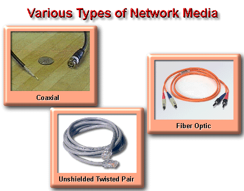
The three primary types of cabling that you'll find in LAN environments include twisted pair, fiber optic, and coaxial. Each has relative advantages and disadvantages that you need to be aware of, both on your exam and in real life.
Twisted pair cabling gets its name from the fact that it's made up of pairs of copper wires that are twisted together in sets of two. The purpose of the twisting is to reduce their susceptibility to Electromagnetic Interference (EMI) and crosstalk. EMI is an issue in environments where devices such as elevators, machinery, and so forth emit high degrees of electrical signal that interfere with the cabling. Crosstalk is an issue whereby signals traveling along one pair of wires interfere with those on another. The more twists per inch of cabling, the less susceptible the wiring is to both EMI and crosstalk.
The most common type of twisted pair wiring is referred to as Unshielded Twisted Pair (UTP). It consists of a group of wires that have an outer casing, but no extra shielding around individual pairs. In contrast, Shielded Twisted Pair incorporates an additional sheathing around each wire pair, making it less prone to EMI and crosstalk. While providing better performance, STP is slightly more difficult to work with, and definitely more expensive.
UTP cabling tends to be defined by a category number. Cat3, for example, consists of two pairs of wires only, and is the minimum requirement for 10Mb Ethernet. This is the same cabling traditionally used to wire phones. Cat5 cable consists of 4 wire pairs, and is the minimum requirement for 100Mb Ethernet. You may also come across Cat5E - this is simple Cat5 cable with more twists per inch, making it less susceptible to EMI and providing higher transmit frequencies.
The maximum cable distance for networks using UTP is 100 meters or 328 feet. As such, it can be fairly limiting when large distances need to be spanned. For connecting to devices, UTP and STP use RJ-45 connectors, similar (but larger) than a traditional phone clip. We'll look at the wiring of those connectors after this section has been completed.
Fiber Optic cabling
A more robust network cabling solution is found in fiber optic cabling. Not susceptible to EMI or crosstalk, these cables transmit light instead of electrical signals, and are capable of spanning much longer distances - anywhere from about 550 meters up to hundreds of kilometers. On the downside, not only are the cables very expensive, but so is the required network equipment as well, including network cards and switches.
Two types of fiber optic cable exist, known as single mode and multimode. Single mode cables can span much longer distances, and only transmit s single signal at a time. Multimode cables actually transmit different signals concurrently, sending data along the media at different angles of refraction. Where single mode cable can travel many kilometers, multimode cable is usually limited to around 550 meters or less.
Connectors for fiber optics cables come in two main types - round ST style connectors, and square SC connectors. Obviously cables should be matched to your equipment types, since they may be different. Examples of LAN technologies than can use fiber optic cables include Ethernet, FDDI and even Token Ring.
Coaxial Cable
While very popular in the past due to their use on Ethernet and ArcNet networks, you will rarely find coaxial cable on LANs today. The two main types of coaxial cable are known as ThickNet and ThinNet. ThickNet can span distances of up to 500 meters, and devices attached to the wire directly using an Ethernet transceiver with an AUI cable connecting to their network card. ThinNet, on the other hand, was a more flexible and thin cable that could span distances of up to 185 meters. Computers connected to the wire using BNC-T connectors. ThickNet is used in the Ethernet 10Base5 specification, while ThinNet is used in 10Base2.
Creating Cat5 Cables
Given how easy it is to pick up patch cables at your local computer retailer, it's no wonder that people take for granted how a UTP cable works. In this section we'll look at how UTP cables are wired, and the different standards that exist.Creating UTP cables properly first requires that you have a crimping tool. A crimping tool is used to both strip the wires, and also to ultimately attach the clip. When buying a crimping tool don't buy the cheapest available - it will almost certainly be useless within a few months. A mid-level tool will tend to cost a little more, but last much longer. Expect to pay about $40 for something half-decent.
When creating a patch cable, you should never strip away more than half and inch of the outer casing to expose the wires. The wires should not be nicked either, or this may lead to performance issues. Bad cables often cause what become "phantom" problems, so you'll want to be sure your cables are created properly. You will notice that Cat5 cable contains 4 pairs of wires, with each solid color twisted with a white cable and similar colored stripe. The proper way to refer to these cables is by the convention:
Solid color = color
White with color = white/color
For example, the green wire is simple referred to as green, but the white wire with the green stripe is called white-green - the background color is always specified first.
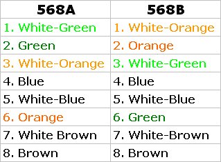
The colors of the wires are important when wiring a network according to standards. Wiring standards are created by the EIA/TIA, and for UTP these are defined in their 568A and 568B standards. While 568B is more popular, government contracts usually specify A, so know both. The table below outlines the wiring of both standards. When looking at the pin numbers, it is assumed you're holding a wire with the clip facing down, so that you can see all the colors. You really should take the time to look at an actual wired cable at this point.
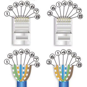
When creating a straight cable, both ends should be exactly the same when held together side-by-side with the clips facing down.
For a crossover cable, one end should be wired according to the 568A standard, and the other according to the 568B standard.
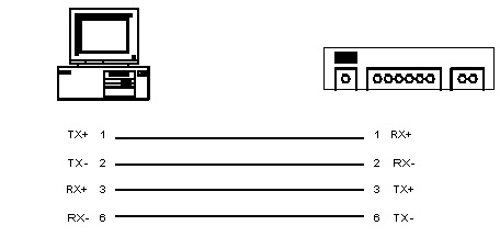
It should also be pointed out that in 100 Mbps Ethernet networks, only 4 of the wires are actually used for transmitting and receiving. The pins used are only those colored green and orange - pins 1,2,3 and 6.
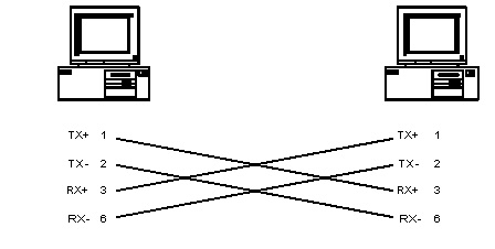
Note the diagram below, which shows a PC connected to a hub. The pins on a network card and a hub port are wired differently, such that the transmit pins from one device connected to the receive pins of another. That is, on a hub, pin1 is a receive pin, and on a PC, pin 1 is a transmit pin.
So when do you use a straight through versus a crossover cable?
Well, as I just mentioned, Network card and hub ports are wired differently, so they use a straight cable. When connecting ports of the same type (such as a PC to a PC, or a hub to a hub), you need to use a crossover cable so that the transmit pins from one system connect to the receive pins of another. Note that router ports are wired like a PC, while switch ports are wired like a hub. Note that an exception exists. Some hubs have a crossover port, which allows this hub port to connect to another regular hub port using a straight cable. In this case, the crossover is internal to the hub. The list below outlines the types of cables that should be used in various scenarios.
PC to switch or hub = straight
Router to switch or hub = straight
PC to PC = crossover
Switch to Hub = crossover
Hub to Switch = crossover
Next we'll continue our look at networking basics by covering media access and a look at Ethernet.