
Home | How Switches Work | Switching and Bridging | Methods | Switching Notes | Intro to Layer 2
Spanning Tree Protocol (STP)
No, not the motor oil! LOLWe have had an introductory look at the need for Spanning Tree Protocol on bridged and switched networks with redundant links. If you recall, without STP a switched network with redundant links will ultimately lead to broadcast storms that are capable of quickly overwhelming a network. In this Study Guide, we'll take a look at specific Spanning Tree terms, concepts, and operations.
The material to be covered in this Study Guide includes:
- Introduction to Spanning Tree Protocol
- Spanning Tree Port States
- The STP Root Bridge
- Port Costs
- Root Ports
- Designated Ports
- Convergence
The specific purpose of Spanning Tree Protocol (IEEE 802.1d) is to prevent loops on switched or bridged internetworks that include redundant links. While mainly used on switched networks today, STP was originally developed for a time when most networks were segmented using bridges rather than routers. This was not only a function of simplicity (bridges are typically less difficult to implement than a router), but also of the protocols in use. While we might take the use of routed protocols like TCP/IP for granted today, there was a time when many networks commonly used non-routable protocols like NetBEUI. In those cases, segmenting a network at Layer 2 was the only real option in terms of controlling network traffic.
Note: The terms "switch" and "bridge" are used interchangeably throughout these Study Guides. You should treat them as one and the same.
When Spanning Tree is implemented on a switched network with redundant links, its purpose is to selectively block certain ports such that any potential network loops that might cause a broadcast storm are eliminated. As such, the physical links that form a loop can be in place for the purpose of redundancy, but only a single path will be forwarding frames at any point in time. Should the active link fail, Spanning Tree will activate one of the redundant links automatically. Unfortunately, it does take some time for Spanning Tree to first of all recognize that a link has failed, and secondly switch a previously blocked port to a forwarding state. Once the network is back to forwarding frames normally, it is said to have converged.
Spanning Tree Port States
On almost all Cisco switches, Spanning Tree Protocol is turned on by default. The reason for this is simple, if it weren't, you might accidentally create a network loop when configuring redundant links. In that way, the default STP configuration is trying to save you from yourself. On many older bridges and switches, STP was often not configured by default, which could lead to some pretty serious communication issues that could be difficult to track down.
On a switch or bridge running Spanning Tree, ports will be in one of four different states. Each of these states is listed below. The transition between states will be discussed shortly.
Listening. In this state, a port is listening to Spanning Tree messages known as Bridge Protocol Data Units (BPDUs), attempting to determine how the network is configured. When in a listening state, a port is not forwarding frames.
Learning. In this state, a port is adding MAC addresses to its MAC address table. When in a learning state, a port is also not forwarding frames.
Forwarding. In this state, a port is sending and receiving data as normal. Once a network has converged, a port will be in either a forwarding or blocking state.
Blocking. In a blocking state, a port will not send or receive any data traffic, but will still listen to STP BPDU messages. When a switch or bridge running STP is powered on, all ports will be in a blocking state.
While the four different STP port states are fairly easy to recognize and remember, the key thing to understand is how the port state will be determined. On an STP network, bridges and switches will pass messages between each other known as BPDUs. These messages are multicasts that are used to determine the STP network topology. An STP switch or bridge will send out BPDU messages every 2 seconds by default. How the information in a BPDU is used will become clearer in the upcoming sections.
The STP Root Bridge
For whatever reason, people tend to become very confused by the terms and concepts of Spanning Tree Protocol. The truth of the matter is that STP is not very difficult at all. At the most basic level, just keep in mind that it's purpose is to ensure that a switched or bridged network remains loop free.
The most important switch on any STP network is known as the Root Bridge. In any Spanning Tree implementation, only one switch holds this role, and this switch becomes the center of this little Spanning Tree universe. The role of the Root Bridge is determined according to an election that takes place on an STP network. Quite simple, when STP bridges first start up, BPDU messages are passed between systems to see which switch will be elected as the Root Bridge. When switches or bridges are running STP, each will have a bridge priority associated with it. By default, all STP switches are configured with a bridge priority value of 32,768. After the exchange of BPDUs, the switch with the lowest priority value becomes the Root Bridge.
Obviously this presents an issue. In most cases, bridge priority values will not have been changed from their defaults, meaning that all switches will probably have the same priority. Because of this, a second criteria is used to determine the Root Bridge as well. In case where more than one system qualifies to become the Root Bridge according to its priority value, the switch with the lowest MAC address will win. In this way, a switch's MAC address acts as a type of tiebreaker. Your goal should be to have a powerful and centrally-located switch act as your Root Bridge if possible. The easy way to ensure this is to configure it with a lower bridge priority value than the other switches on your network.
But why all this fuss about the Root Bridge? Well, other switches and bridges on an STP network need to calculate a path to the Root Bridge in order to determine which of their ports will be placed in a forwarding mode, and which will be blocked. Ultimately, a switch will attempt to place the port with the "shortest" path to the Root Bridge in a forwarding mode, and place all other redundant links in a blocked state. In the case of STP, the "shortest" path is the one with the lowest aggregate port cost to the Root Bridge. Port costs are looked at in the next section.
Port Costs
Much like a Spanning Tree switch has a bridge priority value, so do individual ports. By default, port costs are determined according to the speeds that they support - the faster the port, the lower its associated cost. The default IEEE costs associated with common port speeds are listed in the table below.
| Link Speed | Port Cost |
| Gigabit Ethernet | 4 |
| Fast Ethernet (100 Mbps) | 19 |
| Ethernet (10 Mbps) | 100 |
Ultimately, a switch will use port costs in attempting to determine the Root Port for each and every switch. All non-root bridges will have one Root Port that will be used as the link over which data will be forwarded on the Spanning Tree network. The Root Port represents a switch's lowest cost path to the Root Bridge.
Root Ports
The purpose of the Root Port is best illustrated with an example. Consider the figure below. In it, there are three bridges, and Bridge A has been made the Root Bridge, on account of the fact that it has the lowest MAC address (notice that all bridge priorities are equal). By default, all ports on the Root Bridge are also Root Ports, and have a cost of 0 (Since they are directly connected to the Root Bridge, their cost to reach the Root Bridge is 0).
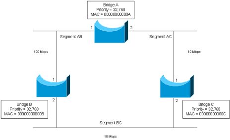
Recall that STP information is transferred via BPDUs. In this case, Bridge A has already been elected the Root Bridge on account of the fact that it has the lowest MAC address. However, the transfer of BPDUs does not stop here - they continue to be sent out every 2 seconds by default. In this case, the Root Bridge will send out BPDUs with a port costs of 0 - remember, it is the Root Bridge, so there should be no cost for its own ports to reach it! These BPDUs will be received on port 1 on both Bridge B and C. When received by Bridge B, it will add its own port cost to the cost provided by the Root Bridge - since the cost associated with a 100 Mbps port is 19, Bridge B port 1 determines that it can reach the Root Bridge with a total cost of 19. Similarly, Bridge C's port 1 (connected at 10 Mbps) will determine that it can reach the Root Bridge with a total cost of 100 (100+0).
Unfortunately, things don't quite end here. Remember that Bridges B and C are also connected to Network 1 and will also be sending out BPDUs on their interface connected to this network (port 2 for both bridges). Let's begin by assuming that Bridge B is sending out a BPDU to Bridge C over this network. In it, Bridge B will announce to C that it can reach the Root Bridge with a cost of 19. When this message reaches Bridge C, it will add its port 2 cost to this value, calculating that it can reach the Root Bridge with a total cost of 119 (100+19) via port 2. Now, Bridge C knows that it can reach the Root Bridge via port 1 with a cost of 100, or via port 2 with a cost of 119. Based on these 2 paths, Bridge C will determine that port 1 (the one with the lower cost to the root) should be its Root Port.
Similarly, Bridge C will send BPDUs to Bridge B across Segment BC. In these messages, Bridge C will announce a cost to the Root Bridge of 100. When received by Bridge B, it will add this cost to the cost of its port 2 interface - now Bridge B also knows that it can reach the Root Bridge (via Bridge C) with a total cost of 200. Based on the two possible paths, Bridge B will determine that port 1 (the one with the lower cost to the root) should be its Root Port.
Designated Ports
Even though we've now determined which port(s) should be the Root Ports on our network's switches, we still need to determine which ports will be placed in a blocking or forwarding mode. For example, Segment BC still has two possible paths to the Root Bridge - via port 2 on both Bridge B and Bridge C. In order to eliminate this loop, one of these two ports will need to be placed in a blocking mode.
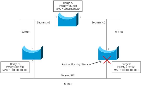
On a Spanning Tree network, each and every segment will have one port chosen as the Designated Port. The Designated Port is the port that acts as the single interface to forward traffic to the Root Bridge, as is determined via another election using BPDUs. For example, in our network, there are three segments - Segment AC, Segment AB, and Segment BC, as shown in the diagram earlier. On each segment, one of the connected bridge ports will need to be elected as the Designated Port. In all cases, this is always the switch port on the segment with the lower port cost. For example, on Segment BC, two paths (via port 2 on both bridges) are available to the Root Bridge, forming a loop. In this case, port 2 on both Bridges B and C have port costs of 100 on Segment BC. Because both bridges have an equal port cost, MAC addresses will again be used to determine the Designated Port, making Bridge B (which has the lower MAC address) the Designated Port on the Segment BC segment. As such, port 2 on Bridge B will be placed in a forwarding mode, and Bridge C port 2 in a blocking mode. Once this occurs, all traffic from Segment BC will exit the segment via Bridge B. This is illustrated in the diagram below.
After learning about the Root Bridge, Root Ports, and Designated Ports, it's time to bring it all together. Once the transfer of BPDUs between systems has determined all of these factors, the network will be loop free. However, the key to understanding the operating of Spanning Tree lies in appreciating what happens when something goes wrong, namely the failure of a link that is forwarding traffic.
Even once the STP topology of a network has been calculated, switches will still be forwarding BPDUs every 2 seconds. These messages serve to inform switches of which links are still active, and which are not. For example, let's say that Bridge B in our example was to fail or be powered down. In this case, Bridge C will fail to receive BPDU messages from Bridge B on it's port 2 interface (remember that a port continues to listen to BPDU messages, even which in a blocking state). After 20 seconds have passed without Bridge C receiving a BPDU on port 2 from Bridge B, Bridge C will assume that Bridge B is not available, and will transfer into the listening state. The listening state lasts for 15 seconds, and is the time when Bridge B will be listening to and inspecting BPDUs from all other bridges. Recall that during the listening stage, the bridge port will still not be forwarding traffic.
After the 15 seconds of the listening state is complete, port 2 will go into a learning state for another 15 seconds. During this time, port 2 will be learning MAC addresses, as discussed earlier. As with the listening state, port 2 will not be forwarding traffic during this period.
Once the learning state is complete, port 2 will transition into forwarding mode, where it will forward traffic as the active path to the Root Bridge. At this point, the network is considered to be converged. It's worth noting the amount of time that passes between the transition from a blocking to a forwarding mode. In all, this constitutes a total of 50 seconds - 20 seconds without receiving BPDUs from the Designated Port, and 15 seconds each of both listening and learning. During this time, no traffic would be forwarded to or from Network 1. While some people might consider this delay unacceptable, it is the cost of obtaining the benefits that Spanning Tree provides in allowing a network to be configured with redundant links.
In closing, the calculation of a Spanning Tree topology is a three-step process:
- Elect a Root Bridge
- Elect a Root Port on each non-root bridge
- Elect a Designated Port on each segment
Next we'll take a look at two additional Layer 2 concepts, namely VLANs and Trunking protocols.